
Advantages of Using Flex PCBs in Your Electronic Project
Using Flex PCBs in Your Electronic Project
Using flex PCBs in your next electronic project is one of the best ways to reduce product weight, cost, and space requirements. These circuits are also more durable, absorbing shock and vibration in high-stress applications. These circuits are made from polyester or polyimide films that can be as thin as 12-120 microns. Conductive materials are then etched onto the surface of the film, with different types of coatings to protect the layers from moisture and damage. Finally, conductive copper is applied to the board to create the pathways for electrical current.
Flex PCBs are often used in consumer electronics like smartphones and tablets, as well as in medical devices that come into contact with patients. These flexible boards can be routed at difficult angles, allowing them to fit inside tight spaces. In addition, they can withstand high levels of heat and mechanical stress. This makes them perfect for use in spacecraft and other high-tech products.
Rigid flex circuits combine the standard construction of a circuit board with flexible components to provide both strength and flexibility. They are used in aerospace, military, and industrial products. Rigid flex circuits are more complex than flex pcbs, and can support more connections. They are better suited for high-volume production. However, they can be more expensive and require specialized fabrication techniques.
In flex circuits, there are several different types of surface finishes that can be applied to the board. These coatings can make the circuit more durable and increase its flexibility. They can also help prevent cracking during bending and thermal cycling.
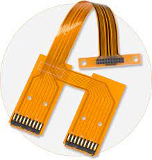
Advantages of Using Flex PCBs in Your Electronic Project
The choice of coatings depends on the environment and circuit design. Tin finishing is a good choice for flex circuits that will be exposed to sunlight, while soft gold coating is ideal for circuits that will be subjected to frequent flexing. Other options include tin/lead, nickel, and black epoxy.
The thickness of the flex circuit board impacts its flexibility. A thinner board is more flexible, while a thicker board is less flexible. In multilayer flex circuits, the copper layer thickness affects flexibility as well. Thicker copper is more likely to crack, so it’s important to choose a thickness that is appropriate for the application. Cross-hatching the copper layer and substrate is another way to improve flexibility.
Via selection is also important in flex circuits. It’s important to avoid vias that are too close together, as they may break during flexing and thermal cycling. To prevent this, vias should be staggered, with larger diameters on the curved sections of the board. This will reduce the stress points that can cause a via to crack or break.
The type of prepreg used to bond flex and rigid sections of the board is also an important consideration. A no-flow prepreg is the preferred choice, as it allows for a smooth transition between the two materials. It’s also possible to use a hot-melt reflow process, but this can lead to poor solderability and reliability. In addition, a hot-melt reflow is not suitable for flex circuits that will be subjected to high levels of temperature fluctuations.



Leave a Comment